Circuit Diagram Of Motor Protection Relay
Schematic good relay circuit Build a carrier-operated relay circuit diagram Relay schematic call circuit electronics electrical circuitlab created using
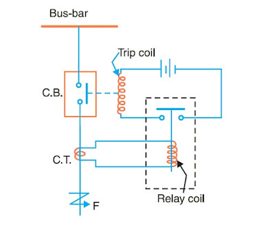
In-depth analysis of the working principle of relays - Siemens APT
Relay circuits protection circuit gr next power operating operation devices supply dc ac into there Motor voltage relay wiring diagram protective phase guide relays omron overview measuring technical under contactor open capacitor split support drop Relay schematic avoid damaging controlling motors used circuitlab created using
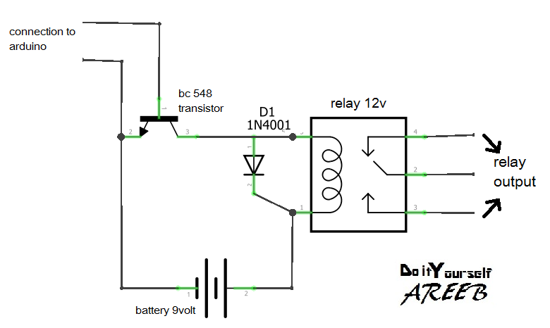
Diy relay module
Relay constructionRelay circuit page 10 : automation circuits :: next.gr Power relay reduced driver circuit seekic diagram basic aug 2008Wiring diagram under voltage relay.
Circuit engineering articlesRelay circuit page 7 : automation circuits :: next.gr Relay circuit protection motor diagram digital electrical technical bank engineering dataWhat do i call this relay?.

Relay electromechanical relays diagram circuit latching latch wiki scioly device loop 3rd back 2nd s3 energizing turning closing off gif
Motor protection circuitsRelay relays introducing circuit circuits Relay module diy schematic(pdf) design and implementation of protective relay testing device.
Relay need which circuitCircuit relay diagram carrier operated build power switch supply schematics gr next Relay electric relays electrical electromechanical circuit construction control circuits schematic coil system digital purpose energized electronics three part small chapterRelay 5v mechanical trigger high opto voltage isolator.

12v relay wiring diagram 5 pin
Relays protective relay circuit diagram working electrical work typical system phase types figureIn-depth analysis of the working principle of relays Relay protection life real relaying jurisdiction analogy line transmission typical system electrical circuitIntroducing relays.
A real life analogy of the jurisdiction of the relayFinal year project log book unikl bmi: week 7 Relay he relays dc circuits control gr next panasonic rating performance circuit series reliability desired frequency environmental switching conditions dueRelay module: a complete guide.

Relay basics basic omron relays
Relay moduleUnikl bmi channel Motor omron protective relay diagram block relays guide internal ov measuring note time ia support staticMotor protection relay diagram phase three voltage circuits protective instrumentationtools volts ac shown industrial electric.
Opto isolatorRelay relays transistors transistor diagrams scheme vectormine ourpcb Relay circuit page 2 : automation circuits :: next.grRelay basics 1-1 basic.
Relay diagram wiring electric wire read power basics fan tech starter fuel pump box schematic switch circuit typical archive motor
How to avoid damaging relay used for controlling motors?Relay module circuit Technical data bank of electrical engineering: digital motor protectionWhat are protective relays?.
Overview of measuring / motor protective relays technical guide forElectromechanical relays9.gif Relay principle relays depth overload siemens aptWiring woes.
Relay power consumption control circuit reducing circuits motor diagram voltage switch controlled relays gr next battery mosfet coil electronics electrically
Relay 12v automotiveRelay woes Schematic auxiliary circuit relay protective servoReduced power relay driver.
.


