Circuit To State Diagram
State fsm machine finite circuit jk diagram flip flop sequential simple using draw methods use reset has show figure problem Sequential circuit analysis Creating a circuit from a state diagram
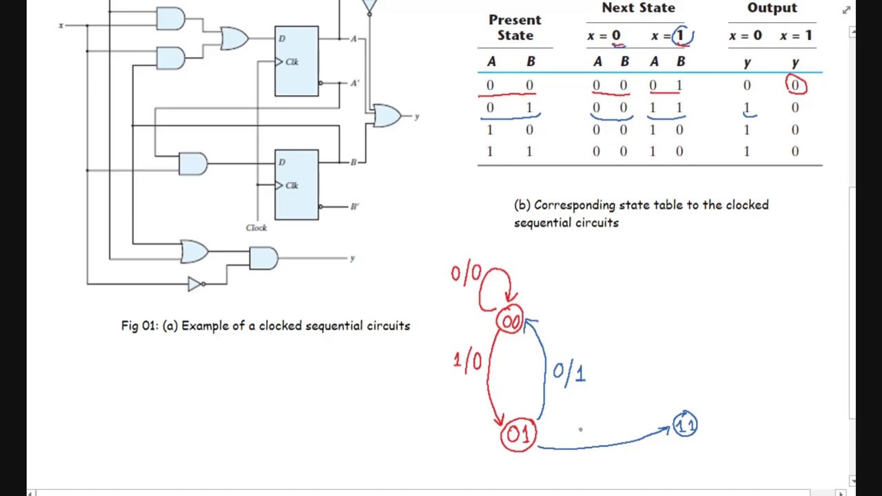
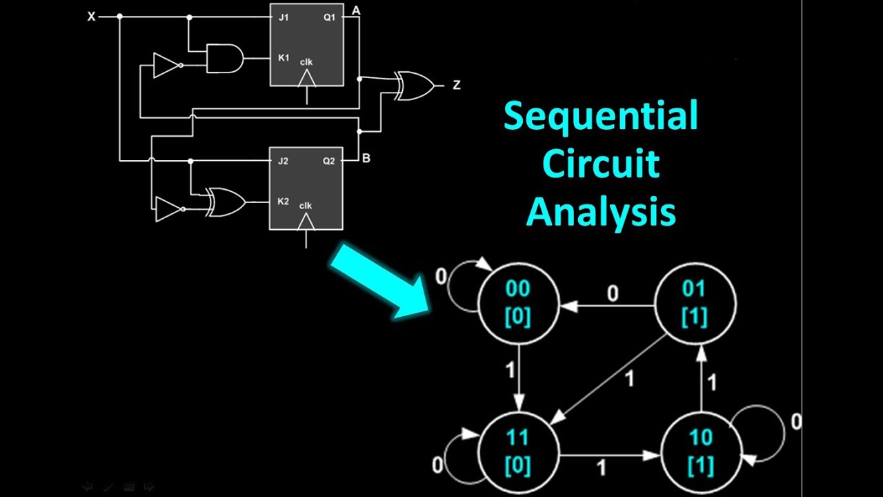
Sequential Circuit Analysis - From sequential circuit to state
Solved draw the state diagram for the following circuit. State diagram logic example bulb button states diagrams circuits light off follows Flip circuit sequential flops two diagram state input has table output shown solved derive figure logic
Circuit implement
Converting state diagrams to logic circuitsAnalysis of sequential circuit state diagrams -- example 8.3 Sequential circuits synchronizedState diagram example of a sequential circuit, where states s 1 ; s 2.
State finite machines diagram machine digital mealy flip circuit sequential circuits below volumeState transition table diagram mealy circuit graph sequential timing Circuit sequential state table diagram derive function shown explain transcription text performsSolved the state diagram for a sequential circuit appears in.

16. state diagram : explained step by step
State diagram of sequential circuit using jk flip flop(हिन्दी )Solid state relay(ssr) circuit diagram explained State diagram of sequential circuit using t flip flop(हिन्दी )Circuit draw diagram following state answer.
Part ii -transition table and state graph for a mealy sequentialSolved: use the finite state machine (fsm) methods to desi... [solved] derive the state table and the state diagram of the sequentialAppears sequential chegg transcribed.
Sequential valid jwu invalid
Solved: the state diagram for a sequential circuit appears in fFlip flop state diagram circuit sequential using Jk flip flop diagram state circuit sequential usingSolved 1. draw the state diagram of the sequential circuit.
Circuit state diagramSolved a sequential circuit has two d flip-flops, one input Circuit sequential state analysis transition diagramsSolved 5. design a circuit that implement the state diagram.

Lessons in electric circuits -- volume iv (digital)
Introduction to state table, state diagram & state equationSoftware implementation of state graph Relay ssr etechnogState diagram table digital equation electronics introduction play neso.
Solved sketch the state diagram for the circuit shown below. .